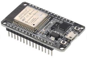
ESP32 Pinout

Here we are discussing about the pinout of the popular 30 pin board ESP32 Dev kit 1.
Strapping Pins:
Firstly there are some pins that is needed to be avoided from using as they are needed to be in a specific state in order to boot and sometimes program the development board. You can only use them when it is necessary but their behaviour can become unpredictable during boot. So it is recommended not to use them. These pins are known as Strapping Pins. These pins are : GPIO0, GPIO2, GPIO5, GPIO12, and GPIO15.
General-Purpose Input/Output (GPIO) Pins:
GPIO pins can be used for general-purpose digital input and output operations. You can use any GPIO pins for connecting to peripherals as input/output except GPIO34 – GPIO39 are input only. They can’t be configured as digital output.
Analog-to-Digital Converter (ADC) Pins:
The ESP32 has 15 ADC pins exposed for reading 12 bit analog voltage levels. These pins can be used to measure analog signals and convert them into digital values. The analog voltage must be in between 0V to +3.3V.
Pulse-Width Modulation (PWM) Pins:
ESP32 provides PWM capabilities on all of the GPIO pins. PWM pins can generate digital signals with varying duty cycles, which is useful for applications like controlling LED brightness or generating analog-like signals.
Serial Peripheral Interface (SPI) Pins:
SPI pins facilitate communication with devices that support the SPI protocol. They consist of four pins: SCLK (clock), MOSI (master out, slave in), MISO (master in, slave out), and CS (chip select). ESP32 has two usable SPI buses (HSPI and VSPI). The default pin selection have been shown on the image above. But different pins can be used as SPI by assigning through Programming.
Inter-Integrated Circuit (I2C) Pins:
I2C pins enable communication with devices that utilize the I2C protocol. The I2C bus consists of two pins: SDA (data) and SCL (clock). In this case it is GPIO21 and GPIO22.
Universal Asynchronous Receiver/Transmitter (UART) Pins:
UART pins are used for serial communication with other devices. They provide two-way asynchronous serial communication through transmit (TX) and receive (RX) lines. There are two UART pins are accessible from the dev kit board. Where UART0 is used for both debugging and flashing the program through USB to UART. So it is not recommended to use. In order to transfer data through UART it is recommended to use UART2.
Interrupt Pins:
Each of the GPIO pins on the ESP32 can be configured as interrupt pins. They can generate interrupts based on specific events, such as a change in voltage level.

