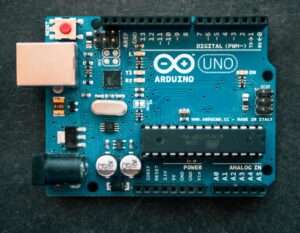
Arduino Uno Pinout
The Arduino Uno is a popular microcontroller board that has a specific pinout arrangement. Here is a brief overview of the Arduino Uno pinout:
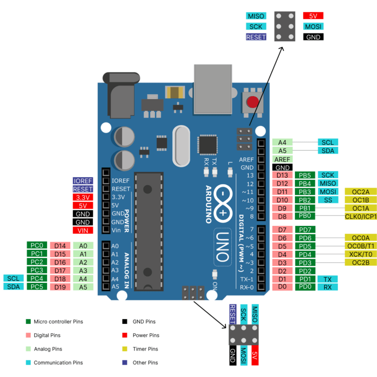
Digital Pins:
There are 14 digital input/output pins, labeled as D0 to D13. These pins support both digital input and output functionality.. Additionally, some of these pins have additional functionalities like PWM (Pulse Width Modulation) and SPI (Serial Peripheral Interface) protocols .
Analog Pins:
There are 6 analog input pins, labeled as A0 to A5. These pins can be used to read analog voltage levels using the onboard analog-to-digital converter (ADC). Some of these pins have I2C communication protocols. In case of a need, these analog pins can be employed as digital input/output pins as well.
AREF stands for Analog Reference in the context of analog-to-digital converters (ADCs). AREF pin determines the reference voltage for analog-to-digital conversions which can be provided externally.
Power Pins:
Vin: This pin allows you to provide an external power supply to the Arduino Uno. It can accept voltages from 7V to 12V
5V: This pin provides a regulated 5V power output. You can use this pin to power external components that require 5V.
3.3V: This pin provides a regulated 3.3V power output. You can power 3.3V components of limited current requirement with it.
GND: These pins are the ground (0V) connections for your circuit. There are multiple GND pins available on the Arduino Uno.
Other Pins:
Reset: This pin serves the function of resetting the microcontroller.
IOREF: This pin indicates the Operating voltage of the Arduino.
Communication Pins:
UART (Universal Asynchronous Receiver / Transmitter): These pins are used for serial communication with other devices without sharing a common clock signal. RX is the input pin, and TX is the output pin.
I2C (Inter-Integrated Circuit): A widely adopted bidirectional interface called the I2C bus enables communication between a master controller and multiple slave devices. SCL carries the clock signal and SDA is used to transmit and receive data in between master and slaves.
SPI (Serial Peripheral Interface): It is a synchronous communication protocol and hardware interface commonly used for short-distance communication between microcontrollers, peripheral devices, and integrated circuits. It typically uses the following connection in between devices to communicate with each other
-
SCLK (Serial Clock): This line carries the clock signal generated by the master, which synchronises the data transfer between the master and slave devices.
-
MOSI (Master Out Slave In): This line is used by the master to send data to the slave device.
-
MISO (Master In Slave Out): This line is used by the slave device to send data back to the master.
-
SS (Slave Select): This line is used by the master to select a specific slave device for communication. Each slave device typically has its own SS line, allowing the master to choose which slave to communicate with.
ICSP Pins:
ICSP stands for In-Circuit Serial Programming. These pins are used for programming the microcontroller with an external programmer, such as when using the Arduino as an ISP (In-System Programmer).
Please note that the pin numbers mentioned above are the logical pin numbers used in Arduino programming. The physical pins on the Arduino Uno board are labeled with both the logical pin numbers and the corresponding Arduino pin names.